Thursday, December 8, 2011


ALATOONA PASS - THE RIDGE

After a very brief consideration D.C. and I had decided to include the ridge to further define the look of this layout section. However, the pass was not in this location. Enter an extreme version of selective compression. The rock point seen here is actually at Dalton, known as Rocky Face Ridge. Alatoona Pass was much farther south. The other consideration to adding an element inconsistent with the actual route was to give up the longer countryside run. The beauty of having a large mainline is to include 'rail fanning' scenics. The fun and realism of watching the runs through stretches of landscape. However after some debate on these two questions the area was too good to pass, pun intended.
Although advances in this scene has occurred, as seen in the Alatoona Pass Label file, this first photo gives you an idea on our starting point.


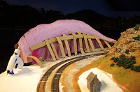
In these series of photos you can see the work that D.C. has begun.


Here, on the left, I am consulting with D.C. as to the ridge size. He took the photos. He then got to work cutting down the 1/4 inch Masonite with a jig saw, attached it to the fascia then added the foam board which he scribed prior to make the bend.

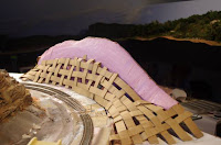
One of the unique aspects of the pass was the steepness. Approximately 80', this provided the perfect element given the narrow area that the mainline will travel. In these next two photos he attached cardboard support strips, compliments of Micro Mark, with the ease of gunned hot wax. This cardboard lattice will support sheets of plaster gauze.

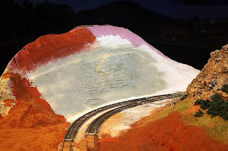
The photo below shows he has added Sculptamold on top of the partially hardened plaster gauze. This is an excellent paper mache material with texture and, as seen here, has been carved. D.C. has added the rock outcropping definition and spray painted the gray as a base before final painting and weathering. He has also begun adding ground cover, dirt 'liberated' from the Alatoona Pass area. The stubs have been added as well and are ready to be wired.


Next time we hope to show you the final scene and perhaps a short video, with trains runnin!

Sunday, October 9, 2011

Anniversary Crew Tributes


Crew Shots


November celebrates the 8th anniversary of the Western & Atlantic RR, North Branch. In 2003 Dick Taylor of RailDreams and one of his modeling associates installed the 25 modules that began the life of this model railroad. If you are new to this site, north branch simply differentiates my W&A version from the magnificent layout by Lebron Matthews. Living in Georgia, Lebron's W&A is referred to as the south branch.

I have been able to call on many modeling friends who have made significant contributions to the evolution of my layout. As a bit of a tribute I made an entry yesterday of the members from the Garden State Central model railroad club. Here are some of my other compadres along with a few appreciative comments.

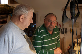
Rhett's talent is super detailing 19th century locos. He converted a Mantua General into a USMRR loco when I planned to include Union operations. View his work by clicking on the Label - Locomotives. Brian is looking at pictures of Atlanta for ideas on painting the backdrop panels. D.C. is taking his 243rd photo, that day.
Brian Kammerrer, Rhett Tyler, the Supt' and D.C. Cebula
Another vintage photo, D.C. and Lebron enjoy a moment of "Train Running for the Confederacy". D.C. and I cut out a section of benchwork for closer access to the Kingston yard. Here he is running his first train using an NCE throttle. The train belongs to Lebron. We were experimenting with operations but mostly discovered a couple of shorts and low voltage areas. Although a little disappointing, we knew where to make the adjustments.
D.C. and Lebron Matthews
Jerry was the proprietor of Keyport Car and Foundry and was a source for link and pin couplers. He was also a wealth of information on early railroading and offered excellent ideas, along with some provocative perspectives, on modeling. Unfortunately Jerry passed away a couple of years ago. We honor his contribution with an Obelisk in the Kingston cemetery.
Jerry Daub with Lebron
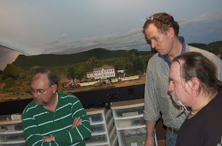
An example of the crew refusing to work! They think working for 10 hours with no break is a little much. Light weights! Actually they're on a break, observing as someone engineers a train on a recently completed stretch of main line.
Lebron, Brian and Christopher Eldridge
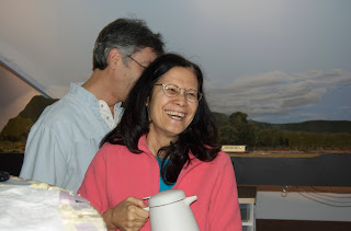
My lovely wife Ku'uipo, Hawaiian, supplying the troops with beverage and vitals.
She has also made a few dozen super trees which now populate Kennesaw Mountain.
Vintage indeed, a 2007 scene of D.C. framing backdrops. This is behind Big Shanty.

Finally we have Christopher posing with his new slippers cutting a fine figure indeed.
 

Saturday, October 8, 2011

Kingston Addition - Barnsley Gardens
The search for appropriate structures can reveal surprising and exciting elements to include into a layout theme. Building a southern railroad, one image is the classic plantation or mansion. I chose Kingston for the site given the area I wanted to cover. My visits to Kingston included trips to a few of these places. My choice was Barnsley Gardens, the contemporary name. At the time it was known as "Woodlands". Barnsley was the name of the plantation owner, Godfrey Barnsley. An Englishman, whose father was a cotton trader, Godfrey built his "Italianate" mansion in the 1840's in the town of Adairsville, just north of Kingston...close enough for selective compression. I was attracted to its uniqueness in form and story. The brick structure was one attraction. Another was that Barnsley landscaped his estate with exotic flora, importing a wide variety of trees and shrubs. This alone I thought would make a striking scene. And although Barnsley traded in cotton, he did not own slaves, slavery being contrary to his beliefs. Matter of fact he paid all his workers. 

Today all that remains are the ruins. However the site is currently used for a variety of public events and, as you can see, is manicured to a similar state as the 1850's. Barnsley was also renown for his unique green roses.  

 Layout Positioning


In these two views the white box represents the approximate estate location. Christopher, my resident finishing carpenter and master modeler, built a knoll to replicate the actual area, according to our research. Kingston is still being developed but is seen by the structures in the right photo distance.

Chris started with mock ups from a print I acquired. Using foam core, and pleased by the workability of this material, he decided to keep this for the final construction. He has been [painfully in my view] meticulous. But as you see, his exactness pays off. The print I mention is shown in the far right photo. 


The nearly complete structure with the creator. Christopher has chosen doors and windows by Grandt Line. The brick walls are textured paper with adhesive backing from Micro Mark. I am almost certain that the roof was metallic. Given Barnsley's attention to detail and financial resource, Chris decided to use styrene and build the roof to resemble copper. He also built Lee & Gordon's Mills which you can or will be able to view elsewhere on this blog.  


Garden State Central Members Visit for a  Work Session


Jimmy, George and Jules are pards from the Garden State Central Model RR Club. We have a web site as well which I encourage you to visit. I became a member around 2003. Everything I ever heard or read about the value of such membership is accurate.  Model RR clubs offer the opportunity to accelerate the learning curve and of course you meet some fantastic people, interesting ones as well.  

This is one of the evenings GSC members come by to work their magic. I try to get these fellas here as often as possible when I am home. Since the GSC has no home members visit one anothers' layouts to either work , run or do both. Here they have converged on Chattanooga to install leads to yard tracks and wire up switch machines. Needless to say having these mates is very much appreciated to expedite layout completion. Speaking of "interesting ones", in the photo above look closely at George. You can see by that mischievous gleam in his eyes he is definitely someone to watch out for. He too has a layout we visit for work and running sessions. Jules, in the red shirt, has been building a very cool garden layout. His website on the links is posted here.

To the left is Bob Judge, one of the founding members and patriarch of the GSC club. Bob is a master at various scenicing techniques and scene building. Here is using insulation foam for contours at the approach to Chattanooga. The backdrop is Lookout Mountain by Brian Kammerrer.


On the right is Butch. Also a member of GSC he excels at kit bashing and detailing rolling stock and structures. Here he is staining ties at the south end of Dalton in preparation for ground cover, real Georgia dirt acquired near Dalton. As we look to bring Dalton to life I'll be posting our progress.  

Sunday, September 25, 2011

Alatoona Pass

INSTALLING the ALATOONA SIDING 

Background
Alatoona is a scene I had as one of my original "druthers". There are two terrific pictures which indicate that it looks to be a major wood cutting facility. One photo, shown below, clearly shows piles of wood to the right which appear were cut for fuel. To the left along the tracks the piles or stacks appear to be cut as ties.


In this picture below, the flat cars appear to have loads of either ties or lumber. The shed in left foreground looks to be filled with fire wood. Side note: for the water tank conversations in our yahoo group site, this picture has what appears to be two water tanks, one round one rectangular. There is one opinion that the rectangular one was built by the USMRR. Not sure yet so more to research; however I am building these as well because the look is too cool to pass up.


The other hook for me to add this scene is the fact that it was on a siding. This was a must to include since there are so few photos of line-side industries. However, once I had the final layout design Alatoona was omitted; the layout area would have been too congested. Forward 10 years... 
Recently the American Civil War Railroad Historical Society group met for its annual convention in Kennesaw GA. Alatoona was on the itinerary. Although I had been considering 'installing' Alatoona and was not committal, this visit was the capper. We walked along the former track route into this MAGNIFICENT cut! I believe about 80' high. There was, still is to a much less degree, a fort known as the Star Fort in the top photo at the top left, which now of course is full of trees. A few us took the hike and there are still remnants of the walls with a few historical placards describing the battle.

Alatoona by Ken Pruitt
When I began my research on the W&A, I met Colonel Bogle who was good friends with Wilbur Kurtz, Kurtz being the consultant to Gone With The Wind and Disney's Great Locomotive Chase. The good Colonel, who has since passed away, told me about this other fella doing the exact same research for the same reason, a model railroad, Ken Pruitt from Michigan. He had many conversations with Bogle who learned a great deal from Mr. Kurtz. I contacted Ken who had become a library of information on the W&A. This scene below was on Ken's W&A. He since needed the space for other domestic priorities...and that's how we have history. Ken has a passion for precision for replicating W&A elements. As you can see Ken was able to combine kit bashing along with scratch building to model an excellent model of Alatoona. In a recent conversation Ken mentioned the long shed was actually built for Sherman's army as a supply depot. The smaller shed housed a saw mill. As a modelling element I would need to omit the long shed given my version is prior to the "invasion" by the Union Army of the Tennessee. But it's too interesting not to include.

The Rectangular Structure

One mystery was, and still is, the rectangular structure adjacent to the water tower. Ken told me that Col. Bogle said it was a sand holding structure to refill the loco sand domes. Supposedly a canvas was stretched the over top to keep it dry. A more recent discovery was this same container as seen in the drawing to the left by a Yank. It shows a spout on the right end, better viewed in a zoom. This structure is also seen in a photo of the Atlanta rail yards but partially hidden.. I guess an argument could be made it poured sand. My intention is to use it as a water tower.


 Choosing Layout Location
Alatoona is actually located north of Big Shanty and south of Kingston. One of the beauties of building a layout is of course the option to alter geographics. My version of Alatoona is north of Kingston on this layout. It is the most open space on the layout. Although a nice uninhabited run on this single track main is removed, it was too interesting to pass up.

This photo below, by D.C. Cebula, shows the area where the siding is to be added. By the way, D.C.also built and carved this rock outcropping known as Rocky Face. The Confederates built a defensive stronghold here to protect the town of Dalton and the railroad, Army of TN's supply line.

There are several criteria that determined this to be the spot. The most obvious was that there was enough approach track; that it did not come right out of Dalton, off to the left, and into the siding. We could have rearranged other trackwork but at this point, after nearly nine years of construction and re-construction, this was to be the LAST track adjustment. Hence this being the 2nd criteria - no other track gets redone!


In this next shot, loose track is being laid out to get the feel for how to install the siding. I rarely use measurement tools, math or other metrics to size up this work. I like the hands-on approach. This could answer a whole lotta questions about other work of mine!


Choosing the turnouts
I inquired extensively about using a curved turnout. Most everyone advised against it, especially if using a stub because of the potential derailments. This being a period layout however, stubs were a must. Working with Hobby Masters train's manager Steve, we perused the Walther's catalog. The coolest find was that Shinohara makes a CURVABLE, turnout; not curved but curvable. I went with this if nothing else to see how it might work. It is simply a straight turnout built as flex track. The beauty of this is that you can line it up so it fits according to the radius already in play. It required loosening the approach track and some maneuvering to line it up. For straight turnouts I simply lay a straight edge along the approach to the turnout. On the curve it is all eyeballing.   

These two photos below show the curvable turnout before and after bending the rail. The head block has been attached to the approach rails to hold the gauge and is ready for linking to a Tortoise. Again, the bending was strictly continuous adjusting and eying up the cleanest transition possible between the approach, or fly rails, and stubs. 


Here you can view the other end of the siding, the north approach, which happened to be nearly straight ;-) going into the siding. 


After cutting the inside ends of the ties just above the frog I was able to bend the straight rails about 3-4 degrees, just enough for a clean joining of the rails into the siding. I applied the same technique using Homesote for a base as described in my section entitled Stub Switches. The length of the siding was determined partially by the length of train I wanted the siding to hold, but mostly by what I could safely fit while keeping a reasonable distance between it and another stop or station.

Once the track is in its final position, a light coating of PL300 is smeared onto the insulation foam to secure the track, then weighted. The fly rails were adjusted for a cleaner entry to the stubs; here they are still too straight.


Stay tuned, even though it'll be another month or so (how about New Year's) before the next posting, hopefully you'll see the addition of the cut as well as the towns of Kingston, Dalton and Chattanooga coming to life as well as the completion of the Howe Truss scene.

Wednesday, March 2, 2011

CONVERTING POINTS TO STUBS

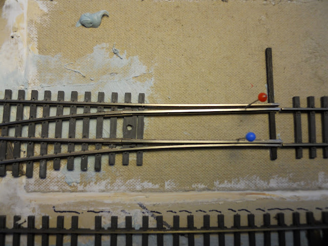
One of the challenges, the many challenges, of building a period layout, Civil War in particular, is determining the degree of authenticity to replicate. This being my first and most likely last layout, I had the proverbial dream of a railroad that appealed to my "must haves" as well as some "druthers", and in the highest possbile caliber. Inspiration came from those modelers featured in the articles, books and vidoes many of us have seen over the years. The only problem for me was being clueless on the immensity of this deavour. Being the novice, and no one in the entire north east to access as a guide or coach for a Civil War layout, I asked RailDreams to construct the benchwork, lay the track and wire the entire layout to avoid what I perceived to be a most painfully slow process requiring the least of my already limited skill sets. They made the bench with 1.5" pink insulation foam. I indicated my desire for stub turnouts. At the very least, I could not see building a period model railroad using points. However, they knowing this was my first layout with virtually no experience and wanting to make this easy, encouraged me to settle for 4 of the 44 turnouts being stub. These would require much less maintenance and provide more reliable operatiing conditions. I conceeded.

Fast forward, RailDreams used point turnouts converted into stubs. Using these as a template I began laying these in Dalton. I chose to start there because I did not want to rip out the scenery between Atlanta and Kingston. However, I did add a siding and a cross over in Atlanta using BK Enterprise stubs which work quite well. As with many aspects of modeling, it is often best to do a practice run; learn what to do as well as what not. As you can see in the above photo of my first turnout, I did not take my own advice. The ties are obviously not well aligned and a quite a few split. My ratioanle...the crew was pressed for time hearing that the Yankees were in Chattanooga.
Laying any track could not be done on the foam, as far as I know, it being too soft to hold spikes, by Micro Engineering . It requires a solid base so I used Homasote cut to fit into the area beneath the turnouts.


This here turnout is a #8. Most are Shinohara. It could be easier to lay from scratch, but I thought this method would expedite the process given the number yet to install. One challenge to converting points is the rail arrangement. The angle requires some creative adjusments. The key of course is ensuring a reasonably smooth and efficient transition to and from the main. You can see there are a number of ties to remove in order to align the rails. The head block is from a copper PC circuit board I read about in MRR, January '86. Another consideration is ensuring a reasonable gap to allow for humidity's influence.

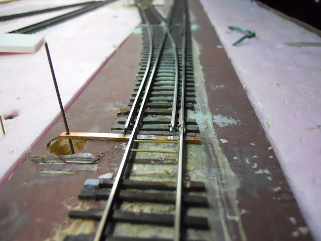
The following two photos are at the north end of the Dalton yards and show completed points to stubs. The piece of foam core sits on the piano wire which is connected to the Tourtiose switch machine below and protects fore arms from impalements.

You will also see brass bridle rods on the approach or fly rails to maintain gauge. The January '86 MRR article explains how these are attached. Most important is using epoxy which works as an insulator as well. Notice the Homesote base on the above shot. The turnout in the bottom photo needed to placed on a piece of pine integral to the benchwork making the drilling for spikes slightly more difficult.


Next I will be showing progress updates on Kingston scenicing, the Oostanaula crossing and Dalton among a variety of other projects. Hope you enjoy the trip. Comments are most welcomed. 

Wednesday, February 9, 2011

Howe Truss

Photo curtesy PictureHistory.com
The W&A was known for having many railroad bridges along its 138 mile line. Over Chickamauga Creek alone there were about 12 crossings. Many of these were covered bridges, two of which we have modeled on the "North Branch". If you follow our yahoo site, American Civil War Railroads Historical Society, you may have read references to my layout as the North Brnach. LeBron Matthews operates his version of the W&A and is reffered to as the "South Branch" since he lives in GA.

Period photos, especially along the Tennessee River and Chickamauga Creek, show remains of bridges and some that were rebuilt. Although slight alterations may have existed, I am more interested in the reamins as they are more likely to be most prototypical.

The Howe Truss pictured above, which crosses Chickamauga Creek, is my template for a  bridge I chose to model.

Researching bridge construction was done through photographs primarily. One find was that bridges were made with 30' timber lengths. I estimated (guesstimated) that these bridge sections, in general, were approximately 90'. This offered the opportunity for a bridge model long enough for that dramatic and more authentic appearance. The model below was built to accomodate three 90' sections spanning 270 scale feet.

At this stage the bridge is completed, abutments have been placed and we are now contouring the river's landscape. Brian Kammerer has been working on the backdrop and has included Lookout Mountain, a most prominent land feature distinguishing the Chattanooga area. I will be sure to include photos of Lookout Mtn. in a future posting.

The following photos are described below the picture.

This section on the W&A is positioned just on the outskirt of Chattanooga. The bridge is constructed with mostly bass and spruce with some balsa. Piers will be a styrofoam core wrapped with a new Chooch product, Flex Wall. I was considering carving the foam but this product is dead on for the actual stone.   
  
Here you can see an error in my modeling of the bridge cross ties. Looking at the period photo these initially appeard to be planks. A thanks to Bernie Kempinski, and my realization on how shadows can be deceiving, I have replaced the planks with standard beams, I believe 8"x8". The pier is this photo is from ARC or AIM (?). I believe someone on our yahoo site mentions this manufacturer in one of his notes as to who manufactures HO piers.


One of the many questions regarding bridge construction was how did engineers join bridge sections. One of my 'senior advisors' and construction engineers, Christopher, while helping me view photos, saw what appears to be a long brace connecting these 90' sections. The piers of course would be placed just below these braces and the section joints.


Stay tuned for more posts as we reach completion.