Showing posts with label Tips. Show all posts

Wednesday, April 19, 2023

Mantua General 4-4-0 Rebuild Part 1

I have rebuilt about 10 of these Mantua Generals. But since Soundtraxx came out with the TS2 1100, I have converted a few to include these beauties. The sound varieties are are superior to their Economi and Micro sound decoders, which I had in several of my locos. Photo below is the General as Mantua manufactured it. I believe the former owner colored the stack and pilot as these were originally black, or if from a kit it would be bare metal. Note the drive shaft. This too was modified as I needed to change the motor to fit the tender along with a speaker, "super" capcitor and the sound decoder.

The most mindful aspect for a rebuild is determining what parts to paint while adding the electrical parts and the new details. 

Where to start?1?1?1 - Contemplate your sequence of moves. It is a bit of a chess match. And as with chess, there are multiple moves. For this build I first chose all the detail parts I wanted to add. Here are two photos showing these. 

Top photo, row left to right: tender steps, water valves, water tank hatch, stack. 

Bottom row left to right: tender brake beams, firewood split from local shrub, short and long handrail stanchions. Later I'll show how these were configured.


Top row, left to right: valve steam rocker arms, whistle, bell, horizontal pilot. 
Bottom row left to right: boiler stanchions, steam chest lubricators, double link coupler pocket, long tool box for rear  of tender.  

Lastly, tender tool boxes that rest on tender top near cab, flag stanchions, pilot draw bar. 

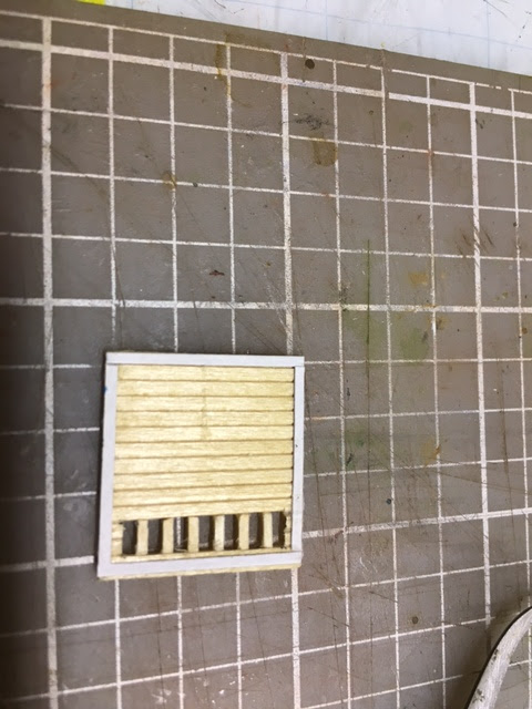
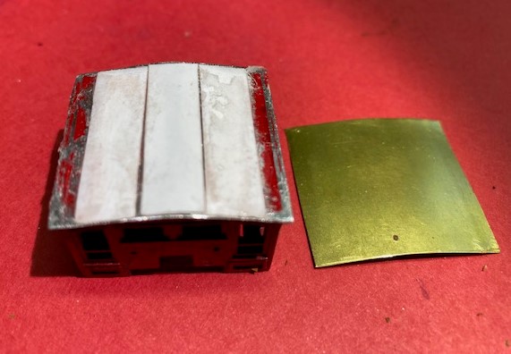
I made notes, both mental and written, as to what I wanted to build. First was the cab roof. Through our civil war railroads groups.io, we learned that  cab roofs were not all peaked as with the Mantua model. There were arched as well.  My good friend Lebron made one and I adapted his approach. First, file off the peak, then using a thin sheet of brass, it is shaped into an arch. Shims were inserted to support the new roof.  


Now to assemble the electrical components. Most difficult to find these days is a strong motor that fits and can accommodate other parts. Here I have a Swiss Micron motor, 13mm x 20mm. The sound decoder, cube speaker and current keeper are by Soundtraxx. Respectfully TS2 1100, 810154 cube and 810140 "super capacitor". I also use TCS KA2 Keep Alives in some locos. Both of these have worked fabulously! Rarely is there a stall or stop over a switch. 

This next image shows the above components installed into the tender. The pointer is indicating the mini plug connecting the hot wire from the decoder to right side drivers. The ground wire is not visible but it's been attached to a screw that was tapped into the tender from. This connects the left side of the tender trucks which also have brass wire wipers soldered to the truck and bent slightly to touch the tender wheels on the left side. The white wire is connected to another mini plug for the hot wire coming from the headlamp. 


Here you can see how the headlamp wires are connected. The ground wire is held in place with the screw that holds the steam dome in place. Duck tape keeps the wires secured to avoid floating into the drive mechanism. 


Here you can see the electrical components, in particular the motor. These unfortunately have significantly increased in price, only available direct from Switzerland. At $90 plus a $16 shipping chang made these impractical to continue using. I am now on the hunt for a successor. Also in this photo you see a few other aspects of the install. One is how the ground wire from decoder is screwed into the tender frame. ANother is the mini plugs. You just cut away the black plastic with cutters. They are then soldered to their respective wire. Lastly is the use of scotch tape to hold it all together, seen also in a previous photo.

The painting of course started earlier. I primed with a Rustoleum paint. The Russia Iron color I found in my collection of Model Power paints. Russia Iron can be a variety of colors. However, this version, from my research, is pretty spot on.
 
Next was the walkway. These could be a mahogany or other hard wood color. I used Vajello a different wood color but after seeing such a difference from the mahogany (photo below), I repainted the walkway to match the cab. 


I predrill all the holes for the detail parts either prior to painting and most certainly prior to adding decals. Here's two photos of cab grab irons. 


The decals are by the master, John Ott. He is a medical illustrator by trade. He also creates remarkable lithographs of 19th century locomotives. http://www.ottgalleries.com

Here are the decals he recently did for me for this build. Impressive no?


I first cut the curved end. The other cuts being square are made after as the hold the decal in place for the free form cut of the curve.

The area to apply decals must be painted white for the decals to show up. I use Vajello white. I tried the gloss white but it was too clumpy. ALthough you can see small ridges in the paint, these are unnoticeable after decal is applied. Micro Scale decal products are quite reliable. 


Once applied, I wick most of the water away in some cases. right photo. But the water helps to loosen the decal to position it, left photo. 


In some cases the decal is a little short. Color matching is ket to cover the white area at tender bottom. Two Polly S colors worked!


Main components are painted and ready to be assembled. Weight is a most important element for these locos. Cabs come with a full weight. However, I like to add the engineer. Using a very slow process of cutting out that corner with a hack saw allows for the figure.
This shows the drive shaft mechanism. You see two shafts. The longer one has NWSL parts because I wanted to narrow the ugly large shaft that comes with the General. I cut one of the large, white balls and drill a hole for the narrow piano wire.

Next time I will show installation of the other detail parts and other nuances to rebuild a Mantua 4-4-0.

Tuesday, September 6, 2022

Flat Figures by Brian Kammerer

Many, many months ago, I needed to scenic the area that increased in size as a result of opening up the aisle just south of Kennesaw Mtn. This area is at the top left corner between Kennesaw and where "Mill" is noted. The entire table of the Atlanta area is now parallel with the back wall and allows for a pleasurable 3' aisle.

I now had 3' feet of new real estate to scenic which I found artistically challenging and was a good thing. I had several ideas including a small farm, dirt road, double post and rail fencing. Mock up  structures were placed in the area. However, it all felt too busy.  Trains would be passing the Redoubt which has perspectives then a farm then mountain... So I just sat and pondered gazing into the bare benchtop. I would come back over a period of about 4-5 months. Interesting how the idea finally lands. I decided that I would create a deep perspective with distance. The backdrop / ridge line is foam core with a couple of layers of flocking. I would  need to show a 1000 yard or more distance from the ridge line to a full size (HO) foreground. 

This photo below shows the first steps to bridging the distance. At the base of the ridge line is a dark tree line. The intent is to show a tree line closer to the viewer and enhance the perspective experience. There are two figures in the middle ground. This is what I call "concept measuring" to ascertain plausibility for the entire scene. The cluster of trees is meant to be a view-through element. Once painted and flocked, I want the viewer to peer through the trees to help distribute the perspective as they see the scouts. The stream, and of course the house car, are the foreground. The fun of creating this scenic element is assessing what to place between the stream and the ridge line to foster the sense of distance.


Close up of the above photo...


Even closer image below. The figure is another Brian Kammerer creation. His film "The Other Great Locomotive Chase" is populated with a plethora of flats. When I mentioned to him what I was doing he suggested flats. I had hoped he would. He graciously created a few sheets of infantry, cavalry and artillery figures. Everyone who has viewed this scene could not tell the scouts were flat.


One of the figure sheets Brain created is below. All I did was reduce the size then print a sheet. After cutting the figures I wanted, and adding a thin sheet of cardboard backing for rigidity, I simply glued a straight pin to the back. The bench is blue insulation foam, making installment of the figures very easy.  


I am getting ahead of my process.

While still in the imagination phase, and driving around on different days, one day as I was passing a field. I saw exactly what I was wanting to build. In the middle distance from the road there was a cluster of trees. The added component missing in my scene was the vegetation among these trees. Small, wild growing shrubs, bushes and some vines. Here is the nearly final touch, close up...


A more distant view...

I want to add more underbrush among the trees and in the open field. However, for the most part, I am quite satisfied with the results.

Friday, June 3, 2022

Test run with a Soundtraxx Current Keeper

 Locomotives running smooth is what truly matters. Otherwise I have a wonderful diorama. But that is NOT the goal. Here are two video shorts showing the Dr Thompson, a converted and detailed Mantua General, on a test run. My big difficulty was getting them to consistently run through turnouts. So far so good!


Saturday, March 6, 2021

Adams Express Group Build Project

 About one month ago, Bernie Kempinski posted a suggestion / challenge for a group build of a box / freight car. The purpose is to generate activity and motivation for those who have wanted or perhaps have stalled on a project. It also can inform members and viewers as to the possibilities to increase your railroad fleet. I chose to scratch build the Adams Express car. As far as we know, there are only two ACW era photos. Interesting in that there are three different types reveled in these images shown below...

This first image, taken in Nashville, has long side openings and an exterior door. The truck side frames are unique in that they are braced with two vertical beams to accommodate heavy loads. One can assume that the color was on the lighter side since the lettering and numbers are dark. A cool modeling detail is the calk marks on the sides. Although they could be considered graffiti today, these were either instructions or notations for the handlers.


This next image shows two Adams cars photographed in Chattanooga, circa 1864...

On the left, a distinct difference from the above is that the door runs on the inside and has a curved roof versus peaked. And seeing white lettering, most likely the color is quite dark. Looking at a photo I took at the Sacramento Museum, it could be a bluish green, seen below this photo.

Back to the Nashville photo, the Adams car to the right has other differences which include a shorter height, a boarded up window and what appears to be an even lighter color with dark lettering.  

Here is a sequence of photos of my partially completed version of the car in the Chattanooga photo...

Siding is Northwestern scale lumber, 1/8" scribed siding, but the planks are too wide. I would use the more prototypical 1/16" for others. The roof is card stock and scored to illustrate a metal roof. I will add Panamint HOT82sACW 3D printed trucks and InterMountain metal wheels. I used metal crate castings for weights and have one door open to see in. Look close and there is a waybill attached to one of the crates. On the other end is a 1/4 oz. weight to bring the total weight to about 46 grams. Alexander link and pin couplers are also attached. Grab irons are Detail West .019 brass wire. Grandt Line  #5101 nut/bolt castings also add to the detail. Turnbuckles are by Tichy. Queen posts I believe are Grandt Line. I found these in a drawer, to my joyful surprise, but were loose so the manufacturer is a guess. Lastly will be to create decals or cut individual letters... oh boy.


Saturday, August 29, 2020

SCHOFIELD ROLLING MILL - ATLANTA

Track-side industry was scarce, even rare in the 1850's and through most of the 1860's. Although there may have been more, I have not researched past 1865 being a stickler for this time period. However, when industries can be identified, especially if my intention is to simulate operations, I will find a way to position it. This became so with a mill just outside of Atlanta, the Schofield Rolling Mill. The photo below shows the remains of the mill taken by the photographer who accompanied Gen'l Sherman during the Atlanta Campaign, George Barnard, in 1864. The remains of a whole lot of rail cars plus a couple of locomotives also fill the scene. Atlanta was under siege and General Hood's Army of TN was in retreat. Abandoning Atlanta required abandoning the trains as well because Sherman's army cut off the rail lines. Consequently, the trains were  intentionally torched. The rail cars also just happened to be loaded with munitions! Hence, the mess. 
There are other images of similar rolling mills, however, this is the only photo of Schofield I could find. And as you can see, there are two tracks. Most likely, but uncertain, is that one track is a passing siding and the other a main. 
You may recall the scene in Gone With The Wind where Rhett is leading a carriage with Millie, her new born and Scarlet through the burning cars in the Atlanta rail yard. That was the a depiction of Confederate soldiers needing to burn the cars and inadvertently so went the mill. Matter of fact, Wilbur Kurtz, consultant to the movie, had the prop builders add a sign to one of the buildings that read MILL. You can see this on photo outtakes of the film.

A close proximity to how the Schofield mill looked is this illustration. The caption lists it as Atlanta-Rolling Mill-1871. Serious selective compression will be required. I am modeling the 1863 version which, with poetic license, compression was required. 
Apparently, production output of the mill included mostly rail and canon tubes. One interesting feature of the structure is that it was open along most walls. This makes sense given the hot summers down south and the need for ventilation. Further research, and help from my buddy Gerry Dykstra, surfaced images of how the interior may have looked. 
This following painting is by von-Menzel depicting a mill in Europe. Many conversations later I was able to confirm that the interior was built of wood beams. Gerry indicated that the floor most likely was iron sheets vs. brick or stone as they would have exploded like shrapnel if hot iron hit it. The vertical beams would most likely have  been wrapped with iron sheet as well about 4' from the floor up to protect against flame. 
This next painting is a mill in Toronto. A big difference here is the roof design. This looks to be an A-type. The Atlanta mill roof was curved, similar to those of the Car Sheds in Atlanta and Chattanooga. Bow trusses will be built to accommodate the mill's curved roof. As you can see, there are a plethora of possibilities to be considered for the interior.

To begin,  I had identified a spot for the mill. The layout expansion not only solidified this plan, it also allowed the inclusion of a passing siding and room for a very compressed model of the mill. This will be north of Atlanta. 


However, the real mill was adjacent to two tracks, the Georgia RR and the East Tennessee & Ga. RR. Location was actually west of Atlanta. The diagram below was done by an on-line friend, Zoe, who unfortunately passed away a few years ago. Her plan was to create a virtual W&A. Although not completed, her research was invaluable. The W&A roundhouse is left, northwest of downtown. The tracks along its left side headed south passed the mill.

Speaking with Gerry Dykstra, he sent me a drawing of the floor plan as he would imagine it, as there is no such drawing, at least in my research. Working off this period photo, Gerry was able to draft a floor plan including rollers, furnaces and other essential elements.

The roof will be 3/4 with the open end of course facing the aisle.
  

Nest step was to build a base. The majority of layout structures are removable. The same is planned for the mill. As I could not find a thick enough styrene, this is a laminate. Quick Grip is THE BEST!
Next was to add the iron plating Gerry mentioned. These were each 5'x7'. It took a few... The gear is from a Faller steam engine model, #180388.
Base done, next was needing to build the roof first because it has a steep curve. Similar to the card shed, the roof is built first then the bow trusses. To built roof a jig was required. The jig is thin sheet metal.
First layer of styrene is little more than paper thin. Roof texture, Evergreen Metal Roofing #4521, is the top layer. 'Bondene' is the adhesive which works GREAT with most styrene, vs. Testors which seems to work only with Evergreen. 

Several sections of the metal roofing were needed to complete the length. Once these were set, next was to add the seems. These metal roofs were made in sections. The material was a tin makeup. The seems represent the soldered sections.

As you can see, MANY of these little buggers were required. Once done I chose a silver metallic spray paint as a base color. Roof was then painted a heavy wash of gray craft paints.

You notice the area where seems stopped. This was to allow the back section of the structure to be attached. The sides were cut from the Dykstra template...


The oval areas were louvers. Once attached as the sides, the roof interior was next. A terrific web site, Textures.com, offers free images. I was luck enough to find wood that matched what we deduced for the ceiling. A key bit of research came from another friend, Charlie who did the Chattanooga Car Shed... O scale! Charlie had this done to full scale; it came out to about 4'. 


For my HO version, another good friend, Jimmy Judge, scaled the Textures.com image to HO. As you see, these were cut into strips as I needed to install the cross bracing first because these needed to be glued directly to the ceiling. The paper would have impeded the adhesion. 

The result was gratifying, especially after some gritty weathering.

Of course I did not recognize the need for corbels as this project was learn as you go. These were willed with my Dremel hitched to a vise and used as a lathe.

Roof completed, work on the lean-to section commenced.  

This roof would be where the chimneys from the furnaces and boilers protruded. The chimneys came out to be the featured element.

Using another Textures.com paper, each chimney required 8 pieces to achieve the look of the period photo.

After many conversations with different construction friends and Mr Dykstra, copper flashing was deduced.


Stay tuned. In another couple of weeks I will have completed adding the bow truss rods, boilers, furnaces, steam engine and steam hammer.