Showing posts with label Scratch building. Show all posts

Thursday, February 5, 2026

Nick Kane's Scratch Built 4-4-0's

 If you have been following Nick Kane's new layout build of the Sacramento Valley, circa 1860, here are two photos of his locomotives. Left is one modeled after the Garrison loco. On the right is the Robinson. 90+% of these gems are SCRATCH BUILT folks!! 


Here is a lithograph of the Globe along with Nick's model of the Garrison in process.

I will be posting more photos and hopefully videos of Nick's layout development and his livery of cars.

Wednesday, December 10, 2025

NMRA AP Entries - Certificate Achieved!

I have embarked on the NMRA AP (Achievement Program). To date, I have received certificates for scenery, structures, author, volunteer, and cars. I was motivated to go this route because a couple of NJ Division Members indicated that I had most of the work done. It was just a matter of completing the paperwork. Here are the cars I recently had evaluated for the Equipment - Cars certificate.

This is Adams Express was scratch-built. The trucks are a unique feature known as a "swing truck". It was designed to handle tight curves. This model is based on two period photos. The one below the model was taken in 1863 or 1864 in the Nashville yards. The other is in Chattanooga. This latter photo was the basis for the walls, doors, and roof, which was tin.


This is a modified platform car kit by Mantua. In addition to the artillery, by Musket Miniatures, I added Alexander link & pin couplers, the device attached to the car which is known as a draw head.


Open top cattle car. This is scratch-built on a Mantua frame. The walls and doors are board-by-board construction.


Conductor's car. Scratch built from two images. These could also be called a Way car and were used primarily for the conductor

A BTS (Better Than Scratch) kit, flat cars were one of many different railroad cars used to transport military personnel. Worst situations was when wounded troops were transported in cattle cars, recently occupied by cattle.


Sunday, March 3, 2024

Harp Stand Build

 Harp stands were the way for switching track mid 1800's. These of course were known as stub switches, the most common turnout configuration until point switches were created.

I had installed a 3 way switch about 10 months ago. My initial throw mechanism was an Arduino. Unfortunately, although it worked, knowing how to program it was WAY outside my wheelhouse!


Necessity is the mother of invention, as the saying goes. And I had more than necessity; I had HIGH need. This is a key area for my operating plans. I decided to use or build my own harp stand. First choice was the PCS hand throw. Al Mueller built one to operate. Unfortunately this stand is good for only a 2 way. I'd need to convert my rail from code 83 to 55 to make that a possibility. That was out of the equation as I had close to 200' of track. Build the harp was the most obvious possibility.

Using the PCS stand as the idea, I did a crude drawing, guessing the size needed. I went with about O scale to give it the length to reach across three rails.


Fabrication of the throw bar positioning cap was a critical build. Overall, my build came with a lot of luck as I measured only the distance the headblock would need to travel to ensure the fly rails reached the outer stock rails.

Initially I used a tri-corner file to start the cut for each of the three slots to hold the throw bar position. 


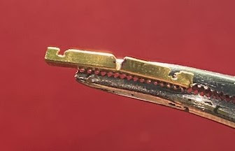
Next I used a razor saw. With a cross cutting motion I sawed the edges as well as the depth. This gradually created the tree openings large enough to hold the piano wire throw bar.  

Fabricating the legs and frame required 2 sizes of KLM angle brass stock. Angle was chosen for greater stability. The way to bend the angle is to make a notch which reduces an awkward bend and a cleaner angle in the leg.  

A quick touch of solder and the two legs are secured. The other half has been built and secured.


Spacers were inserted to ensure clearances for the headblock and throw bar movement as the reinforcing side panels were secured. 

Here is the Arduino servo that my friend Ray Russell built and helped me install. Unfortunately, however, the programming was too technical for me which led me to build the harp. 

The image below shows the harp installed and I am shiming the base, made from flat brass stock.