Monday, November 27, 2017

CHATTANOOOGA CARD SHED Part III

A brief recap on the roof construction begins with the jig. One unexpected 'plus' was the aluminum flashing purchased from Home Depot. It was was 2' long and 1' wide, the exact measurement I needed. Funny thing is, I had arbitrarily decided on the shed size to fit the layout pace. SOMETIMES we catch a break! Scrap plywood fashioned the base.


The roof was constructed with 2 sub-sections of .010 sealed with Ambroid ProWeld. The finished roof is 4 sections of Evergreen V Groove #4250 also sealed with ProWeld. My initial attempt, disaster, JB Weld was used which, after a couple of days, separated and was easily pulled apart. These photos are the 2nd attempt; as of today the roof is holding tight!
A distinct construction aspect of this roof is that you can see the seems running across the roof as well as a gutter.
This is the key reason for choosing the V Groove styrene. To model the seems, which on the actual structure were soldered. I used Evergreen part #111 to model the seems. Testers liquid cement was used to attach these into the V groove slots.
Here is the new roof completed including the gutter which is three layers of Evergreen part 102 off-set to mimic the photo. Next is to add about 80 corbels. The "final" phase is the cupola with approximately 32 windows, 64 louvers and 100 corbels. 


Saturday, November 25, 2017

NMRA OPEN HOUSE


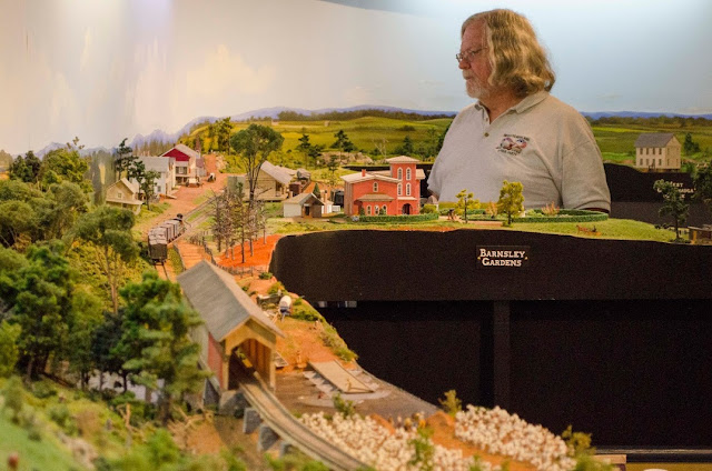
November is open house for those model railroaders affiliated with the National Model Railroad Association. This is in addition to the local Divisions who sponsor Division Meets throughout the year where members also open their layouts to visitors. The following photos and video is from 11.18, last Saturday and although not a bright sunny day we had a reasonable turnout. The gentleman below with glasses, Dick Genthner, has been a long standing member of our Division and is a very accomplished modeler. Any compliment from Dick is one to appreciate.
 

Overlooking the Atlanta rail yards is Dick with another Division member, Herb, who also has been a terrific model railroader. Both gentlemen have established layouts conducting operations on a regular basis, one of my goals. 

Newest engineer on the W&A, DC Cebula, is running the locomotive Alabama of the Georgia RR which had an interchange in Atlanta. This view is overlooking Kingston. The interchange here was to the Rome RR, not Italy of course.
 
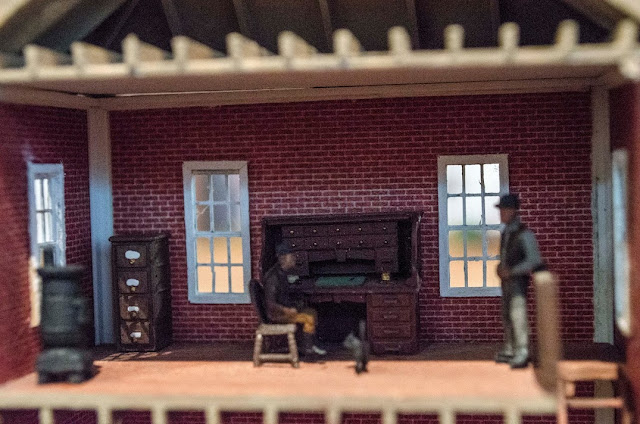
From inside the Macon & Western depot office. Windows were framed inside. Rafters and floor joists by LeBron Mathews.
 
Other photos and videos are forthcoming. But for now, here is a montage of videos shot by our good friend Andy Salcius who also took the photographs.


Saturday, September 30, 2017

TRAIN RUNNING ON THE AQUIA LINE, RICHMOND, FREDRICKSBURG & POTOMAC RR

Our group, the American Civil War RR Historical Society, had our annual meet here in Harper's Ferry. Our site visits include Harper's Ferry of course plus the Martinsburg Roundhouse facilities and Bernie Kempinski's O scale model of the Aquia Line, otherwise known as the RF&P. It was heavily traveled by the USMRR as the Yanks were continuing their push into VA. Here is a video of three 3-man crews operating according to a live schedule of train movements at his home in Alexandria.

http://usmrr.blogspot.com/2017/09/we-have-met-layout-and-it-is-ours.html

Friday, August 18, 2017

SHAKE DOWN RUN

This was time to see just which locomotives would run reasonably well to terrible, and to detect track malfunctions as well. Two of  my club mates from the Garden State Central Model RR Club in NJ came by. Below is Jimmy flying our colors on his tee shirt. Beginning in Atlanta, he engineered the Catoosa to stops in Big Shanty and Kingston for a final stop in Dalton. However the Catoosa gave him (and me) fits of unplanned stops and stalls. 
Below, Martin is in Dalton with the famous General locomotive. He is setting up to reverse the loco on the Dalton turntable in order to run freight south over to Kingston. It was not unusual to have locomotives pulling trains but not long distances. The General has been one of the more reliable locos in my stable. For this session it had less difficulty than Jim with Catoosa.
Jim hovering over Atlanta while Martin continues his reversal.

Looking south as Martin pulls the General from the turntable. You may also notice that we use the NCE DCC system; love it!
The session was fruitful. BIG lesson, which never fails to appear, is the need to have clean track and wheels!. My frustrations ran up watching the Catoosa struggle. The next day I began troubleshooting. I realized that I although I had cleaned the main line, I had Jim and Martin running onto sidings that had not been cleaned. Pulling another loco off to inspect, I discovered the filth on the driver wheels. I am sometimes surprised if not shocked as to the amount of dirt the wheels collect in a short amount of time. However, these Mantua 4-4-0's require as much contact as possible to ensure smooth running. Although I accept the fact there will be the stalls and stops, these can be dramatically reduced by handling the Ops Session Fundamentals 101... a thorough cleaning of ALL track and wheels prior to ops sessions. But we did have fun!

Sunday, July 30, 2017

CONSTRUCTING SPLIT RAIL FENCE

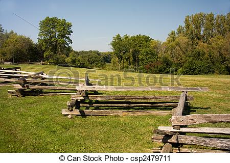
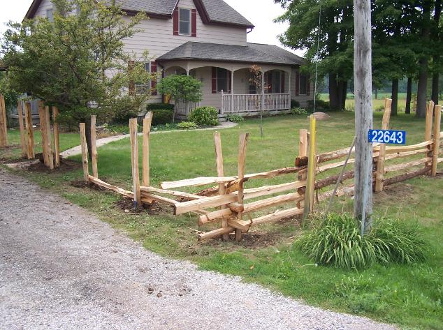
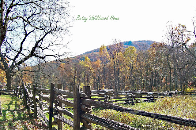
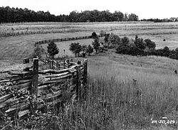
19th century fencing took many forms such as snake or worm fence, some refer to it as zig-zag. Rails would be stacked four to nine rails high...


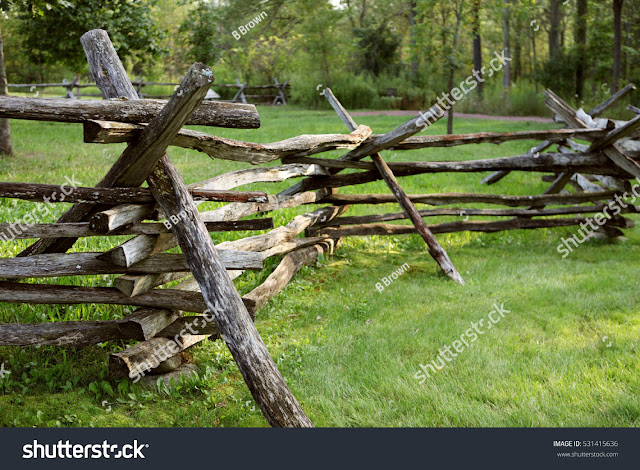
Another style is what I call double post or simply split rail...

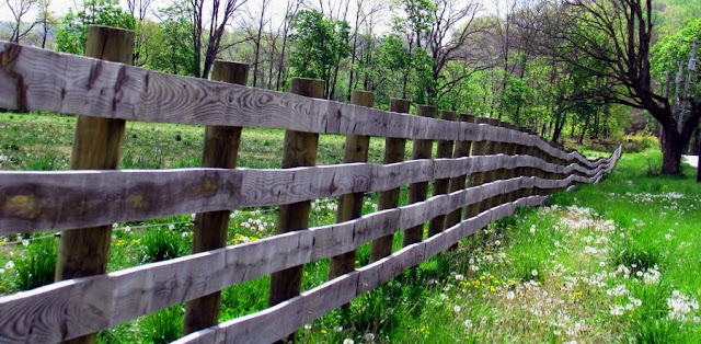
...which could be five to eight rails high given the purpose. Eight high were usually to coral live stock, horses in particular. Often times fencing was to demarcate property lines as well as to keep free ranging live stock out of fields with crops. More urban areas could have picket and plank fencing. 

 
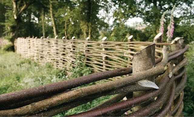
I discovered one type I refer to as a woven fence, made from saplings...

This post focuses on creating the double post split rail fence. 
Step 1 - The easy part was acquiring material to make the split rails. Local Starbucks or other morning coffee providers usually have wooden stirrers. At least they did several years ago. when I amassed my inventory. 
Step 2 - Cutting the stirrers into narrow rails. Initially I used a #11 Xacto. Then I realized I could use my miniature band saw from Dremel. These are cut into four sections, lengthwise of course. No need to make these perfect. Remember, splitting rails left various angles and shapes given the gain. When folks like Abe Lincoln, known for his skill at splitting rails, went about splitting, they used wedges, sledges and axes. 

Step 3 - Sanding the woody hairs and shaping these initial cuts to add more angles. A tool I have found very useful is my Delta sander; it quickly does the final shaping.

Step 4 - Decide on rail length. My research has been mostly via internet photos. However, parks and battlefields are a terrific source. Many of these places look to authentically recreate their sites, often including fencing. I found lengths of 7', 8', 9', 10' and 11'. For the double post fence I chose 11'. Here's where the Chopper comes in very handy. Set the barrier, make MANY rails. Posts are cut 5'; 7'-8' if to be inserted into the scenery base.
Step 5 - Construction. Lay out a piece of double stick tape the length you want your fence. Next lay out the posts at 9' intervals, seen below.
 This allows for  a 9" to 12" overlay of the rails shown below.
Next is to begin laying the lower rails in every other gap, at the bottom of the post. The second level of rails covers the open spaces. Continue to alternate until you reach the level desired. I chose six rails high. Most photos I saw showed this height. I use carpenter's glue as it drys in about five minutes.
Now the staining. I use two craft paints. One is FOG, the other is Barn Wood. Making a wash in a small bowl, I drop a bunch in at a time, swish 'em around then separate them on a paper towel...
Once dry I make a stain from black India Ink and Isopropyl alcohol, 70%, and repeat as in the prior process with the wash. 
Building straight sections are easy in that they can be done on a flat surface shown in a prior photo. But when the need is to make angles or turns I build in place...
No worries about the sheep. They were just exhausted from running around avoiding hungry troops. 

Wednesday, May 17, 2017

CHATTANOOGA CAR SHED - UPDATE

Latest photos show the completion of three walls. In a prior post on the shed, I mentioned that I used Chooch flex wall and Micro-Mark Factory Red Brick adhesive paper. These were formed over the base wall made from a double layer of plywood to get a good thickness for strength. You will notice one wall has the limestone pillars painted a light gray. This was a test that I found very satisfactory. It is a medium wash using a craft paint named FOG from Michaels art supply. 

 
Next was to create a jig to build the trusses / roof supports as seen below. I used the upper edge of the end wall as the guide to place #18x5/8" wire brads. The jig base is  left over piece of pine. The trusses are Pastruct #90655. First was to cut off the one beam in order to get it to flex then removed one of the remaining V sections from each end. So far I have 8 completed with two more to build. Next will be constructing the roof; I plan on using Evergreen sheet styrene, part #4250, V groove .040" thick. Each section is 6"x12". Amazingly, the foot print I made was perfect such that I did not need to cut to fit any section. Four sections laid side to side fit perfect!
Fast forward... creating the jig is usually the biggest challenge and that was no different for the roof. But how to get the .040 styrene to bend and hold its bend was a conundrum. A few conversations later with friends, they suggested a heat gun. But I needed a solid base to allow the styrene a solid base to reform.  So a small jig was built. Scrap 3/4" particle board was cut into arches in line with the ends of the car shed to accommodate one section of styrene. Aluminum flashing was to be the solid base and secured to the arches. 


Anchoring one end of the styrene with clamps, I moved the heat gun over the surface until the plastic began to relax. One great idea from Ray Russel to help hold the new shape was to place a cold towel immediately onto the styrene to lock the position. In the end and although it came out reasonably well, the problem was that I could not count on each styrene section to remold itself into an exact position so that all 5 sections would line up cleanly. I need to be bale to have a solid even arch base to shape these .040 sections. Why .040? Because they have the V grooves far enough apart to replicate the solder joints shown in the photos!
Sharing my dilemma with club members, Steve Lang suggested taking two .020 sheets, glue them in the shape of the arch and that could serve as a sub roof to hold the .040 sections in the arched position. "But Evergreen doesn't make them 1'x2'." Steve did have sheets that size - exactly! Love how a plan can come together.
Starting with old 3/4" plywood you can see I cut 8 arches and secured to a base. 
I was unsure how to clamp the roof and then the duh moment... 
add spacers.
 JB Weld epoxy was my choice to secure the aluminum; speaking of which, it was also the exact size needed when purchased, 1'x2'. Very happy several materials were ready to use.
 Here is the jig with the sub-roof being prepped, limed up.. 

The two .020 sheets were lined up on the aluminum and clamped. Leaving one side clamped, the other side was opened in order to apply the Ambroid PRO-WELD. I went to a much larger brush and wider container since the accompanying brush was way too small when I needed to get a lot on quickly. But it worked.
So far so good. However there was a slight uplift to the sides of the sub-roof. I am hoping that by clamping the V groove sections onto the sub-roof using JB, and onto the aluminum jig to hold the curve, the end result will be close if not spot on.
First is to line up the V groove styrene sections.
 One edge was then secured with clamps to hold the position.
JB Kwik (5 minute epoxy) was applied to the other edge. After that hardened, waiting about 1 hour to cure, three more applications with hardening time has one section secured. Below two sections are in place. The other two sections are place holders to ensure alignment.


Thursday, February 16, 2017

Chattanooga Car Shed

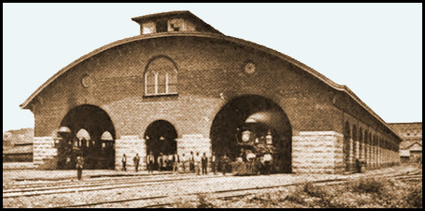
Chattanooga is an end point on my W&A line. One of the 'signature' elements is the relatively much photographed train station. At that time these structures were called the 'Car Shed'. It is a term used in larger cities along the W&A such as Atlanta and Dalton. However, the smaller towns depots and stations were usually constructed of brick or field stone. My challenge was to find a material that replicated the limestone pillars as seen in the photo below...
Finding no textured material, I did locate a paper product of limestone block from Miniature Planet. However, when I went to purchase this they had discontinued that particular design... figures. I had used a flex wall for another project manufactured by Chooch. Problem  was that it did not bend on tight corners as needed for these small pillars. Fast forward to a couple of weeks ago when I took my first trip to the incredible Springfield train show. Speaking of which, it was well worth the trip from NJ. But that's another story. Fortunately I met the owners of Chooch. Their idea was to score the corner to make a clean bend at the tight corners. He also suggested how to alter its color with a gray wash. I purchased the HO/N Small Cut Stone, #8260, and found it to work fabulously! The scoring idea was perfect and it took the wash remarkably well.
Here is a sequence of pics from package to install... 

The wall starts out 4"x24". It is very easily cut with an Xacto #11 blade or a single edge razor. Most important of course is to accurately measure and mark the corner for scoring. I used ply bass wood as the frame. While scoring the flex wall I accidentally cut all the way through the Chooch wall but not the backing material. But that was not an issue. These walls have an adhesive backing and stick very well. In some cases I used hot glue because then narrow sections did not adhere well and the hot glue worked fabulously. I also decided to clamp the interiors to ensure adhesion. 
Below is the sample of how the walls will look once assembled. Next is to tackle roof construction. More on that later.